|
Videos Taig Mill Duet3 Control |
Duet3 /
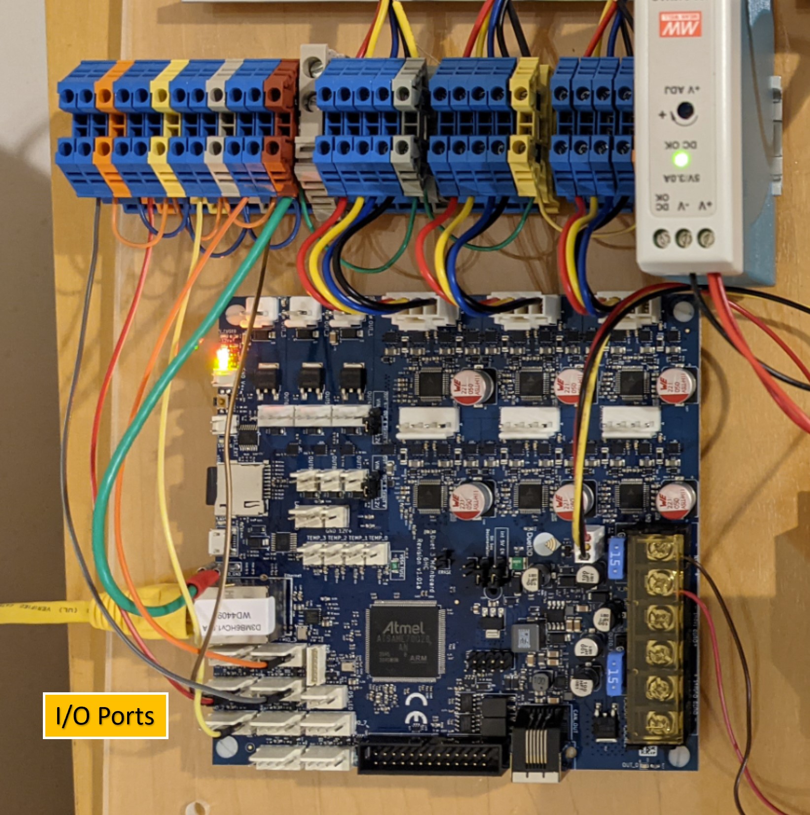
EndstopsLimit Switch (Endstop) ConfigurationWhy use Limit Switches?Despite what you may have heard, limit switches (imho) are not positioning devices. They are a reliable way to define physical machine limits. Yes, switches may be repeatable to better than a mil but that's not their point. I only rely on a limit switch accuracy when I've reset the board for some reason and realize I oopsed and need to keep machining. No, by homing a machine and defining careful physical axis limits what happens is that you won't smash the head into something or try to go off the end of the bed while running G-code. Reprap carefully stops the machine and tells you the move is out of range. It happens to me on my heavy CNC router probably once a week or so when I forget to set a Z or don't realize a bit is too short or thought the origin was elsewhere. WiringThe Duet3 supports many kinds of limit switches or endstops. I'm going to use standard switches for now, but it easily supports inductive sensors and optical sensors. I've temporarily wired the connectors for stock 2-wire endstops plus a shield. Each switch is wired into pin 4 (IO.in) of an IO Port and ground. The ground connection is made at the DIN terminal block and goes to a single common ground on one of the ports. The switch can be NC (Normally closed) or NO (normally open) but NC is recommended for safety. I'm using NC because it is recommended and because I was unable to get reliable results using NO. I think the un-terminated sense wire was picking up constant noise because homing stopped prematurely 20% of the time. The Taig is very bad at grounding due to all the anodized aluminum. 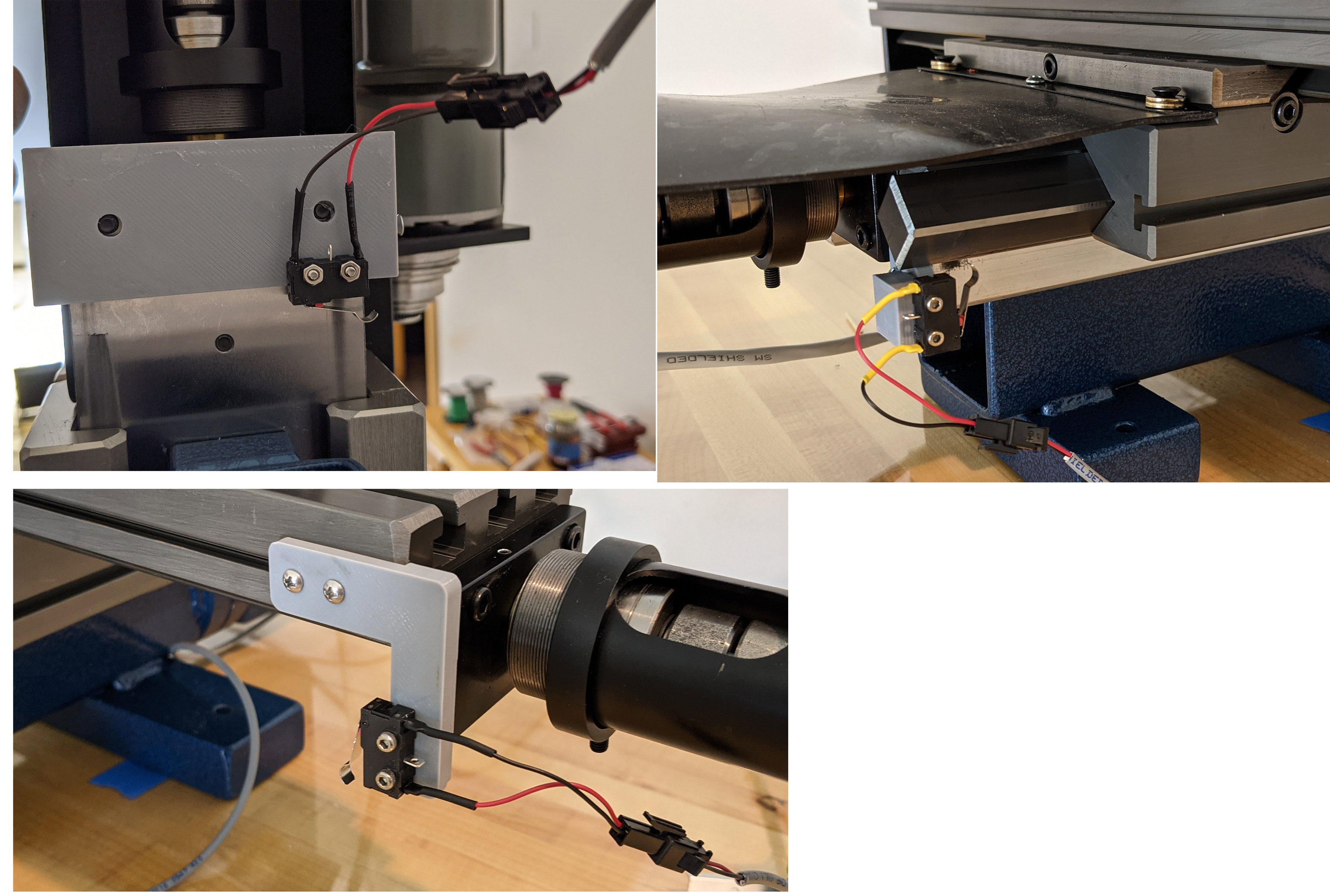 The 3d printed mounts and XY limit switches. The mounts were from this great article. I changed the holes for my much-smaller microswitch and shrank the Y mount but otherwise it's right from the article. SoftwareConfigurationThe following lines defines my pins for use in the XYZ max limit switches. The actual ioX is arbitrary and it's easy for me to change them. This was the random order I plugged them in at. ; Endstops ---------------------------------------- M574 X2 S1 P"io3.in" ; x maximum using active high M574 Y2 S1 p"io2.in" ; y maximum using active high M574 Z2 S1 p"io1.in" ; z maximum using active high Homing ScriptHere's the homex.g script that homes the X axis G91 ; relative mode ; speed of 200 is set to avoid thunking into the switch G1 H1 X300 F200 ; move in the +X direction, stopping if the homing switch is triggered G1 X-4 F200 ; move slowly 4mm in the -X direction G1 H1 X10 ; move slowly 10mm in the +X direction, stopping at the homing switch G1 X-5 F400 ; move to the left for a little slack... G90 ; back to absolute mode G92 X265 ; and set Xmax here G1 X230 F800 ; move over a little Final NotesOver time I moved the Z endstop to the right side of the column. In an enclosure, it was too hard to maintain on the back of the column. Also, here's a video of it homing at 4x speed.
|